
Robert Dunn
James Gabel
Group member E-mail addresses.
 Table of Contents
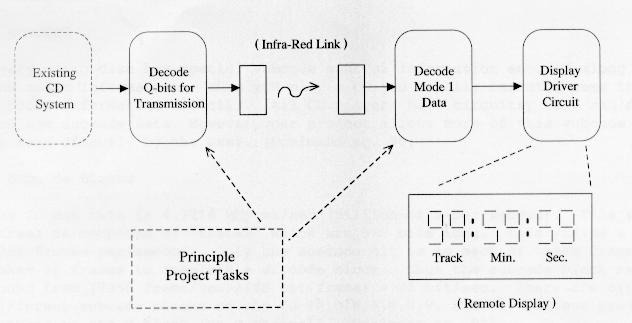
The project goal was to investigate and design an interactive remote control.
This would result in a wireless
system to remotely display musical Compact Disc Q-Bit Subcode information, see
Figure 1. We needed to decode and display Q channel
Mode 1 data--data from the music areas on a CD. The specific data displayed
is the "Track Number"
(TNO), "Time-In-Band" of the song being played, "Absolute Time" of the CD
being
played, and control data such as Stereo or Quad recording. Our main challenge
was how to "decode" the desired subcode information from the serial
data stream of the CD. Such a feature would not only be innovative, but would
be a benefit to those who have trouble seeing the display of a regular CD
player.
Figure 1. System Overview Diagram.
In developing the specifics of our project, we made sure we addressed these
three project criteria:
The project will be composed of several distinct parts. Of primary
importance is capturing the Q subcode data from the CD disk. Since this
information is normally routed to the display, finding this information is
a matter of discovering where the Q data enters the display driver
chip. With this found, a small IR LED driver would broadcast this
information. Because the relevant simplicity of building an IR link to
transmit the data, we concentrated on the decoding the Q channel data from the
player.
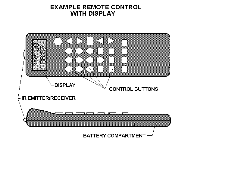
In the remote display device, an IR detector would capture the IR
transmission. The signal would be adjusted for gain, and then decoded by a
display driver. The display driver would connect to a LCD display, which
would show the same information as that on the CD player's main display. Such
a prototype is shown in Figure 2.
Figure 2. Sketch of remote control with Q-bit
data display.
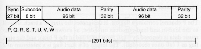
Q-bit subcode is 98 bits long and is stored in the subcode region of every 291
bit long frame of music
on a compact disc (see Figure 3). In each CD
frame, the Q-bit subcode occupies a single bit. Because only one subcode bit
is in
each of these frames, it takes 98 frames to complete a subcode block. The Q-
bit subcode block rate can be determined by taking CD frame rate (7350
frames/sec), and dividing it by the number of bits to compete a frame (98
bits/frame). [2]
Figure 3. Position of Q-bit subcode in each CD
frame.
The Q channel can be in three different modes. Each mode
describes different information about the track and CD:
Objective
Q-bit Subcode
Q-bit subcode is the term for the information on a compact disc that holds the
track number, track length, and time in track. Every music disc has special
subcode control information encoded along with the music information. The Q-
bit subcode has several modes, which distinguish the type of information the
code
carries. When you play a CD you cannot access the subcode information
directly. All CD players have circuitry that can decode and use subcode data.
Some of this Q -bit subcode is displayed on the front display of a CD player.
This information, such as time in track and track number, is useful for
determining what song is being played, and how far along the song is. There is
other useful information in the Q-bit subcode, such as absolute time in the
CD.[1] Our project allows more of this subcode data to be
available for the user.
(7350 frame/sec)/(98 bit/frame) = 75 bit/sec
Thus, 75 times a second, the Q-bit information is updated.
Our project decodes and displays Mode 1 data, but
data from the other two modes could have been decoded. [4]
Figure 4. Information in Mode1 Q-bit subcode
block.
| Control Bit # | Function | Zero-Bit | One-Bit | 1 | # of Channels | Stereo | Quad | 2 | undefined | -- | -- | 3 | Copy Permit? | no | yes | 4 | Pre-emphasis | off | on |
|---|
The first control bit is where "the number of audio channels" (two or four) is indicated. Control bit number two is not used at this time. Control bit number three is "the digital copy" (permit/deny) bit. This bit "regulates the ability of other digital recorders to record the CD's data digitally." [7]
With control bit number four, "pre-emphasis (on/off) is indicated. The player reads this bit and automatically switches to the appropriate de- emphasis circuit." . The standard de-emphasis for a CD (when used) has a flat response (0 dB) from 20 Hz up to about 3 kHz and then rolls off to about -10 dB at 20 kHz. "By attenuating high frequencies without affecting overall signal frequency response, the signal-to-noise ration of the signal may be improved." [8]
Mode 1 during track play also contains other data of interest:
Figure 5. Information stored on the Q-bit subcode
block.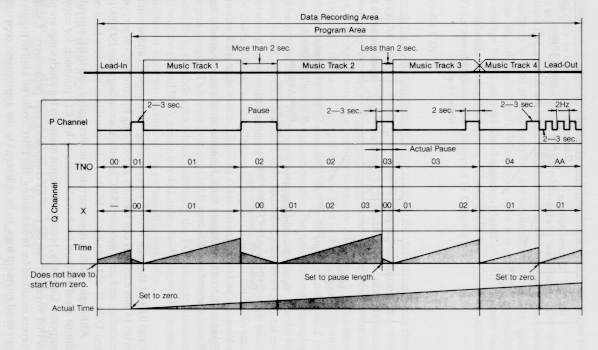
All of the time and track number information is coded in the Q channel as an 8 bit word representing two-digit BCD (binary coded decimal). The first four bits represent the tens-digit and the second four bits represent the ones- digit. Each digit is decoded from the BCD representation in the following standard:
| Decimal Number | BCD 4-bit Word | -------------- | --------------- | 0 | 0000 | 1 | 0001 | 2 | 0010 | 3 | 0011 | 4 | 0100 | 5 | 0101 | 6 | 0110 | 7 | 0111 | 8 | 1000 | 9 | 1001 |
|---|
The IR link has become common place for consumer electronics today. The
relative simplicity allows their use in many applications, from
calculators to remotes.
In our proposed consumer product, a remote control would have in addition
to the standard equipment, an infrared photodetector, a decoder
chip, and a small LCD display. The display would show the user, at the very
least, the track, and time in track in minutes and seconds.
An additional feature would incorporate new commands into the remote control
transmitter. The controls would allow the user to control what data was seen
on the display. For example, the user could toggle between displays showing
track number and time in track, absolute time in the CD, time left in the
song, and absolute time left on the CD. Most of this information is already
present in the CD's mode 1 Q-bit subcode.
Because of the large number of infrared projects proposed for this quarter,
and that one group member had already built several, it
was decided to forgo producing a hardware IR link as part of this project.
Creating the IR link would not have been too difficult. The serial information
of the
Q-bit subcode data could be easily transmitted over a IR link with little
modification. In the remote control, the entire Q-subcode package would be
composed of a photodetector, a single integrated chip, and a LCD display. Thus
the receiver would be part of the integrated circuit. Because transferring
data has been done remotely, it will not be repeated during this project.
The time line used for completing this project was set up into the following
parts:
The first step in this project was finding the Q-bit Subcode Data. In most
compact disc players, this data is separated from the audio information at
some
point, and sent to a display driver circuit. At this point, the data is in
serial form. We needed to find the points where probes would be installed to
find this data. The group tried several of the CD
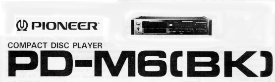
players in the lab, until we found a model which was well
suited to the project. The Pioneer PD-M6(MK)
compact disc player has as a feature, a Q-subcode port on the back of the
player. Figure 6 and Figure 7
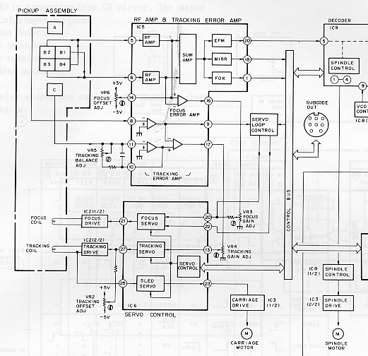
show a schematic and block diagram of the Q-bit Subcode portion of the player.
Figure 6. Schematic of CD Q-subcode port on Pioneer
PD-M6 CD player.
Figure 7. Block diagram of CD subcode port on
Pioneer PD-M6 CD player.
The next part of this project was decode the Q-subcode data. The group
needed to see how the data was fomatted in order to interpret how to decode
it. The data could not be displayed on a standard oscilloscope. A Philips PM
3580 100 MHz
logic analyzer was used to capture and display the bitstream coming from the
Q-subcode data port.
We next experimented with available equipment to decode and display the
subcode data. We found that LabView from National Instruments
was available in the design lab in the University of Washington Electrical Engineering
department. However, the only hardware available for data input to the
LabView software was a GPIB (general purpose interface
bus) interface card. GPIB is an interface system through which interconnected
electronic devices communicate.
TECHNICAL ELEMENTS: For development of our project we used three elements:
(1)- CD DATA SOURCE
For our project, we used a Pioneer PD-M6 CD player which had a Subcode output
jack on its rear panel. This output was made available for "future audio
applications." From this jack we used the "Sub-code Q output" serial data
signal and "Sub-code serial output" sync signal. These signals are generated
internally from the player "decoder" IC. We acquired a set of manuals on this
CD player to determine which jack signals to use and in what format these
signals were in. The data structure was not shown in the service manuals.
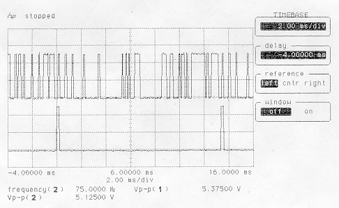
Our first task was to find the Q-subcode data. After the subcode data was
found, the digital signal was displayed on an oscilloscope. Figure 8 shows the Q-bit subcode block signal and its sync
pulse signal. Figure 8.
Oscilloscope plot of a Q-subcode block.
We used a Philips PM 3580 Logic analyzer (at North Seattle
Community College) to determine the structure of the Q-bit subcode data
coming from the CD player. From this experiment we verified that the first bit
in the subcode serial stream is the S0 bit. Thus the S0 bit is sent out first
as the most significant bit (MSB). We also confirmed that the numeric values
such as track number are in two-digit BCD format.
(2)- CD DATA Acquisition System (Tektronix TDS 320 Oscilloscope & GPIB card)
For design test purposes our system uses a digitizing oscilloscope and LabView
software to emulate a decoder system, see figure 9, CD-
BITS.VI. This experimental system is basically a 98-bit serial to parallel
converter. The actual product would be created using the same decoding
algorithms implemented in compact circuitry including PLDs (programmable logic
devices).
Figure 9.
Diagram of the CD-BITS.VI LabView Virtual Instrument.
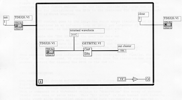
A Virtual Instrument (VI) is a software construction that has characteristics of a bench instrument. Figure 9 shows a diagram of CD-BITS.VI, the main VI
file in our system. An overview of this figure follows. On the left, outside
the large box is the control icon for initializing the GPIB to the Tektronix
TDS 320 oscilloscope when this VI is first started. Next, the VI control goes
to the large box which makes iterations of the internal functions in an
infinite loop or until you interrupt it. The internal functions, as followed
from left to right are:
This sequence continues until you interrupt it. When the "Stop" button is
clicked, VI control is sent from the iteration box over to another control for
closing the GPIB to the TDS 320.
(3)- DATA DECODING
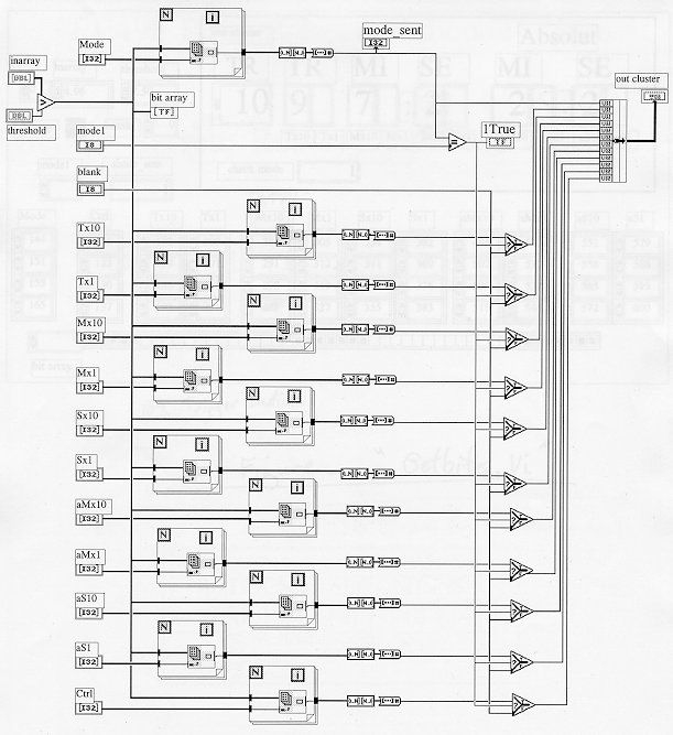
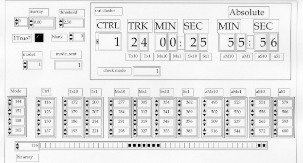
Our experimental decode software is shown in Figure
10. An overview of this figure follows. In the upper left, the "inarray"
is an array of numeric values of the voltage waveform of the sampled data from
the oscilloscope. This is compared to a threshold voltage to "discretize" the
array of voltage levels into ones or zeros bits. This "bit array" is then
bussed into indexing blocks which allow controlled selection of bits
representing the desired Q-channel data. There are twelve of these indexing
blocks, each with a different set of index pointer inputs. The index pointer
labels and their functions are:
Beyond this indexing are some conversion functions to present the data in the
proper form for the output cluster display. Note that the "Mode_sent" data is
compared to the "mode 1" constant. When they match the "1 True" data line is
high (true) and the other indexed data is passed on to the out cluster.
However, if the "Mode_sent" data and "mode 1" constant don't match, then the
"blank" word of zeros data is passed on to the out cluster.
Figure 10.
Diagram of the GETBITS.VI LabView Virtual Instrument.
Once our LabView virtual instrument was running, we calculated indexing values
to pick out the bits we wanted from the Q Channel serial data stream. These
numbers are shown as the index arrays near the bottom of Figure 11. We focused our work on displaying the mode
number and the mode 1 control bits, track number, track time, and absolute
time. Our system uses a digitizing oscilloscope and LabView software to
emulate a decoder system. The actual product would be created using the same
decoding algorithms implemented in compact circuitry including PLDs
(programmable logic devices).
Figure 11.
Control Panel of the GETBITS.VI LabView Virtual Instrument.
In summary, the Q-bit subcode data takes the following path. The Q-bit,
separated from the audio information on the CD, is sent to the display driver
IC (on the Pioneer, it is also sent to the Q-bit-Subcode port). The scope
probe is connected to this port. The oscilloscope captures the Q-bit subcode
serial data waveform. The oscilloscope sends the packet to the computer via a
GPIB computer interface, and on command sends the packet to the computer. The
LabView software then takes the waveform, and converts the waveform to a
binary matrix. We use an adjustable threshold value to determine what voltage
levels constitute a binary "one". The locations of the data needed for
numeric conversion are indexed in the subcode. The resulting data is then
converted into numeric values for the display.
EXPERIMENT RESULT: The result of our experiment was a better understanding of
the Q channel serial data stream. The 98 bits per frame are sent with the
most significant bit (MSB) first. Numbered data such as the track number
(TNO) are sent as four-bit BCD words and so eight-bits are needed to represent
the tens-digit and ones-digit of tracks up to 99. Eight bits are also used in
BCD format to represent two digits of the minutes and seconds from 00 to 59.
TECHNICAL PROBLEMS: We had to quickly find a method of reading in real-time
data from a CD player. We settled on equipment in one of the engineering
labs.
One problem with our system is the remote display is two seconds
behind the actual time on the CD player. This is caused by the slow
nature of our GPIB interface. This delay would be corrected when PLD's are
used, which would allow a real-time display of the information.
PROTOTYPE PERFORMANCE: The computer-based model of our decoding and display
algorithm performs well and is easily adaptable for experimentation. Figure 12 shows an active representation of the data
display for the consumer. For our development software all forms of the CD
data are visible on-screen. You can see the raw serial stream of the CD
player, any of the individual bits, and the final numerical display of the
desired information in the Q channel data.
Figure 12.
The Data Display for the Consumer and the Raw Waveform (CD-BITS.VI).
We have made the LabView VI files that we developed available for FTP
downloading, however, you may need to make adaptations for your specific
equipment or application. Our VI files also require other LabView VI files
for the Tektronix TDS 320 which should be available in the standard LabView
3.1.1 installation (in the TKTDS3XX.LLB in the VI.lib library). The LabView
VI programs can be FTP downloaded as a zip file:
SIGNIFICANCE: Our results prove that the Q channel subcode from a CD player
is easily decoded and all of the information can be displayed for the
consumer. The results of this project show several things. First, the project
has shown
how the Q-bit subcode data can be shown on a device external to the CD player.
Second, it has been shown that this information can be more detailed than that
the display on the CD player itself shows, including: Quad or Stereo, copy protect, and inner track frame number. Even the time remaining on the disk can be calculated by subtracting the absolute time from the total disk time. The simple logic used in the
LabView software can be incorporated directly into a single integrated chip.
The single integrated chip allows for the device to be compact enough to be
placed into an remote control without increasing the size of the remote by a
large amount.
FUTURE OPPORTUNITIES: Our experimental algorithm presented in this report may
now be implemented in a digital hardware circuit. The circuit could also be
integrated with an off-the-shelf IR transceiver and an LCD package for a stand
alone prototype system. We hope future CE EE498 students consider all or part
of this and have as much fun learning as we did.
Several more things could be explored if more time was available. Information
from the Mode 2 and Mode 3 Q-subcode could be displayed. There is additional
information in each song which tells about the year the song was created, and
the country in which the song was produced. A look up table would be needed in
order to correlate some of this information.
ACKNOWLEDGMENTS: We thank Professor Blake Hannaford for giving us insight to
the core of our project--the data and encoding used in CD players. We
especially appreciate Mr. Chris Prall, a UW alumni and LabView beta tester,
for giving us a quick-start with LabView. We also thank Mr. George Andexler
and Mr. Gregory Lipski for loaning us manuals on the LabView software and
helping us use the lab equipment.
[1], Pohlman, Ken, The Compact Disc Handbook, 2nd Edition
, 1989, A-R Editions Inc, Madison Wisconson, Page 91.
[2], Ibid, Page 90.
[3], Ibid, Page 91.
[4], Ibid, Page 92.
[5], Ibid, Page 95.
[6], Ibid, Page 94.
[7], Ibid, Page 83.
[8], Ibid, Page 83.
[9], Ibid, Page 97.
[10], Pioneer Electronic Corporation, Pioneer PD-M6(BK)
Compact Disc Player Service Manual: Repair & Adjustments , 1986, Pioneer
Electronic Corporation, Tokyo, Page 31.
[11], Pioneer Electronic Corporation, Pioneer PD-M6(BK)
Compact Disc Player Service Manual: Circuit Mechanism Descriptions , 1986,
Pioneer Electronic Corporation, Tokyo, Page 3.
[12], National Instruments, LabView Instrument I/O VI
Reference, 1993, National Instruments, Dallas, Pg. 1-5.
IEC 908: 1987 "Compact Disc Digital Audio System" Standard from the
International Electrotechnical Commission (IEC).
Serial Infra Red
Remote Transmitter
IR-related ASCII Schematics V1.00
North Seattle Electronics &
Engineering Technologies Division. North Seattle Community College has the
digital analyzer used in this project.
Personal Computer Infra Red Remote Control
For further information on National Instruments and LabView check out these
web sites:
FTP site with LabView Vi
Files
Hewlett-Packard designed the GPIB (originally called the HP-IB) to
interconnect and control its line of programmable instruments. The GPIB was
soon applied to other applications such as inter-computer communication and
peripheral control because of its 1 Mbytes/sec maximum data transfer rates.
It was later accepted as IEEE Standard 488-1975 and has since evolved into
ANSI/IEEE Standard 488.1-1987. The versatility of the system prompted the
name General Purpose Interface Bus. [12]
The goal of out project is to investigate and design a method for a wireless
system to remotely display musical Compact Disc Q-Bit Subcode information.
We want to decode and display Q channel Mode 1 data- data from the music areas
on a CD. The specific data displayed will be "Track Number" (TNO) and "Time-
In-Band" of the song being played. Other possible data to display is the
"Absolute Time" played on the CD.
The main challenge: How to "decode" the desired subcode information
from the serial data stream of the CD.
Above minimum plus:
11/13 (Monday)
11/15 (Wednesday) Project Proposal with Schedule (this document)
11/20 (Monday)
11/27 (Monday)
11/30 (Thursday) Project Presentations and Demos in Lab
12/04 (Monday) WWW Pointers of Report due by email to Prof. Hannaford
12/06 (Wednesday) Edited Reports Returned
12/11 (Monday) WWW Pointers of revised report due by email to Prof.
Hannaford
Robert Dunn Infra Red Link
Project Procedure

EXPERIMENTAL DATA SYSTEM
Technical Results

Project Discussion

 Notes and Sources Cited
 Sources Cited
Other sources used but not directly cited:
NOTES
History of GPIB

Project Proposal -November 16, 1995
Project Criteria
Project Deliverables
Minimum Deliverables
Maximum Deliverables
Project Schedule:

Email -- stangman@u.washington.edu
Web --
http://weber.u.washington.edu/~stangman
George Barrett
Email -- gbar@u.washington.edu
Web --
http://nsccux.sccd.ctc.edu/~electron/div-fac.html
James Gabel
Email -- jgabel@u.washington.edu